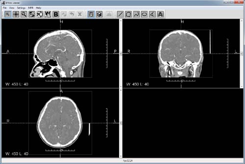
InVols GUI interface in 2D mode.
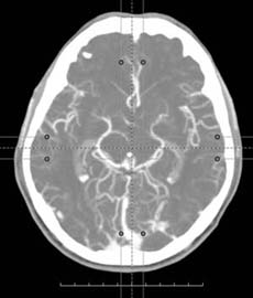
In order to quickly evaluate the possibilities of InVols viewer just run example_ct_head_256.bat script in the program folder. The script will run the program with instruction to open test dataset (Datasets/ct_head_256.raw) for visualization. The dataset is essentially a downsampled CT-scan of contrasted brain vessels, the original data is 8 times bigger (2 times by each dimension). But you can download additional test dataset that were not changed anyhow: http://ngavrilov.ru/invols/index.php?id=Download. When InVols loads the dataset you will see something like this on the screen:
InVols GUI interface in 2D mode.
By default InVols enters in 2D mode. To switch into 3D mode press ![]() on the tools panel.
on the tools panel.
Menu items:
Description of all InVols tools and their functions depending on the currently used mode:
| 2D mode | 3D mode | ||
|---|---|---|---|
| Translation of MPR center, translation and rotation of reference lines, measurements and their vertexes translation | Translation of the bounding box vertexes | ||
| 2D image translation | Camera translation | ||
| Image zoom in/out | Camera zoom in/out | ||
| Oblique section rotation | Camera rotation around its center, which by default is situated in the middle of the bounding box | ||
| Brightness & Contrast alteration (window level & window width, WL) | Shifting window center and narrowing/widening window width for the window-level parameter, thus changing current transfer function | ||
| Choose WL from wl-presets | |||
| Reset all settings to the defaults, delete all measurement objects | Reset all settings to the defaults | ||
| Cutter | |||
| Cancel last cutter action | |||
| Cancel all cutting | |||
| Switch to 2D mode | |||
| Switch to 3D mode | |||
| Show presets redactor | |||
| Start measure distances | |||
| Start measurement of squares and average densities inside a contour | |||
| Start measure curve lines' distances | |||
| Start measurement of squares and average densities inside an ellipse | |||
| Start measurement of angles between two lines | |||
| Delete all measurement objects |
There are two ways to load dataset into InVols environment:
It should by noticed that in this mode InVols uses bicubic filtering to render two-dimensional images, which is crucial for small features visualization.
In 2D mode dataset is visualized using Multi-Planar Reformation (MPR) technique, visualizing 2D images of sections in orthogonal and arbitrary(oblique) planes. At start only three orthogonal projections are reconstructed: sagittal, frontal and axial. To navigate in the dataset in 2D mode choose ![]() on the tools panel and then drag MPR center (intersection of reference lines). You can also use scrolling with the mouse or scrollbar on the right of 2D view.
on the tools panel and then drag MPR center (intersection of reference lines). You can also use scrolling with the mouse or scrollbar on the right of 2D view.
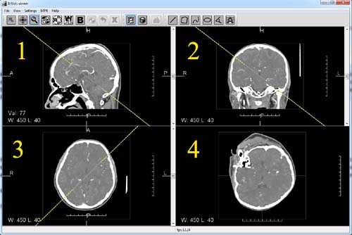
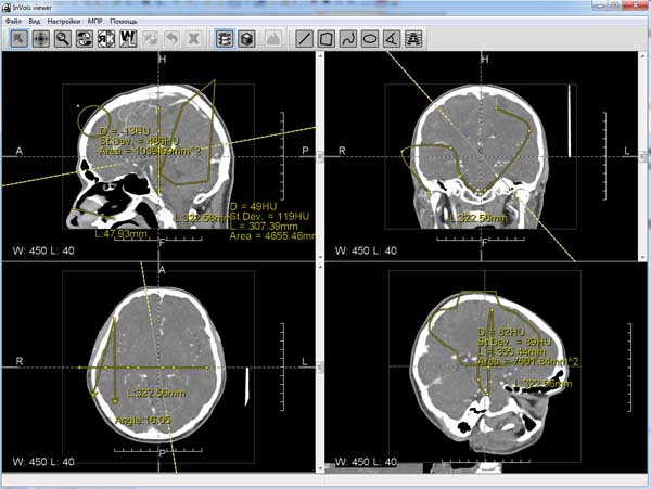
Sagittal (1), frontal (2), axial (3) and oblique (4) projections in 2D mode.
In order to see oblique section in the fourth window start rotating one of the reference lines pulling their margin areas as illustrated further:
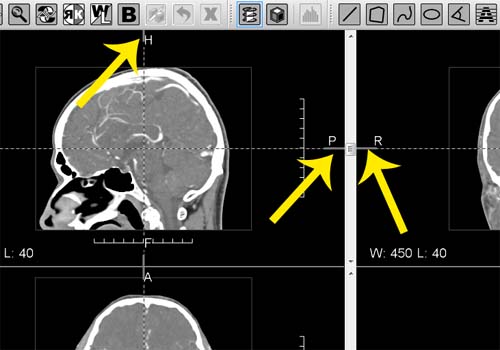
Rotation of reference lines in MPR mode to get oblique section. Pull lines areas that are close to the border.
When oblique section is built, you can rotate oblique plane either rotating the yellow line on orthogonal views or rotating the plane itself in the forth window using ![]() tool.
tool.
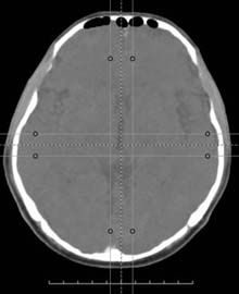
InVols allows for the slab mode in MPR, i.e. it allows to change thickness of the section (slice). Thus there are different ways to calculate 2D image in MPR mode:
 |
 |
 |
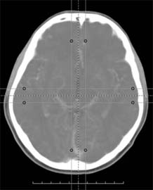 |
| Native tomogram image | Maximum Intensity Projection | Minimum Intensity Projection | Average Intensity Projection |
Available measurements:
Different measurements in 2D mode.

3D mode in InVols.
Left mouse button in 3D mode has several functions. These functions depending in the chosen tool are presented below:
| Drag bounding box vertexes (see illustration bellow) | |
| Camera center translation | |
| Camera zoom | |
| Camera orbital rotation around the center | |
| Shifting window center and narrowing/widening window width for the window-level parameter, which works the same way in 2D mode | |
| Cutting tool |
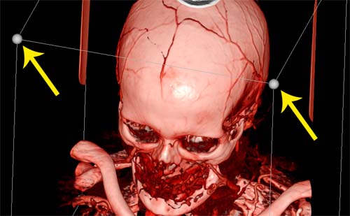
Vertexes of the bounding box in Volume Rendering mode.
Right mouse button in 3D mode always rotates camera around center.
Middle mouse button (wheel) in 3D mode translates camera center.
Wheel rotation (scroll) performs zooming.
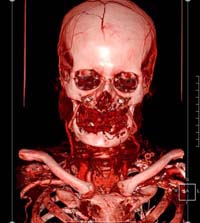
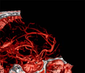
Preset, or transfer function (TF), is a rule by which DVR algorithm renders a spatial point depending on the density in it. For a given density value TF returns colour and opacity. Thus DVR represents volumetric dataset as a semitransparent heterogeneous cube. Areas with density for the air are usually made transparent in order to see the object.
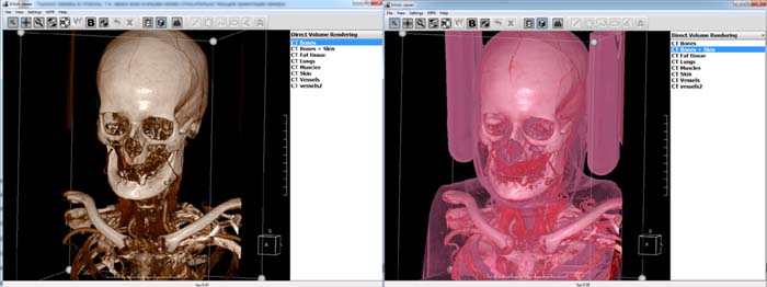
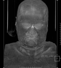
Two different transfer functions (presets) for the same dataset.
In order to alter current preset choose ![]() tool to open presets redactor. You can also doubleclick on an element in presets list on the right. In the redactor user can change preset control points positions and their colors. Point x-coordinate corresponds to data density and y-coordinate corresponds to opacity. Points color corresponds to the color of the points in the space where data density equals points density value. Between any neighbour control points their colors and opacities are lineally interpolated thus setting colors for the whole density range between points. Besides, densities greater than any of those of control points have last control point's color and opacity. Densities before the first control point are transparent.
tool to open presets redactor. You can also doubleclick on an element in presets list on the right. In the redactor user can change preset control points positions and their colors. Point x-coordinate corresponds to data density and y-coordinate corresponds to opacity. Points color corresponds to the color of the points in the space where data density equals points density value. Between any neighbour control points their colors and opacities are lineally interpolated thus setting colors for the whole density range between points. Besides, densities greater than any of those of control points have last control point's color and opacity. Densities before the first control point are transparent.
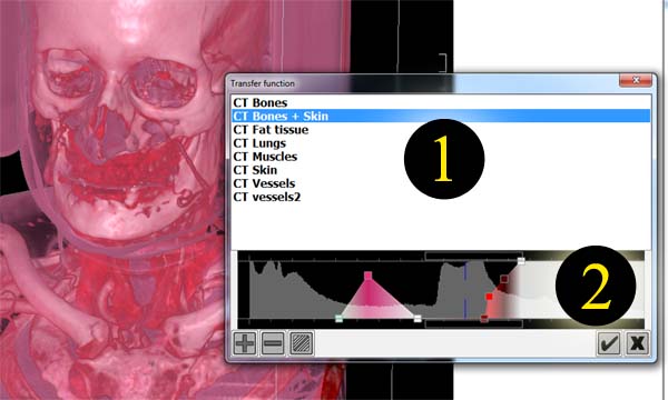
Presets redactor: 1) list of presets. This list is the same of the one in the main program window. 2) Histogram and editable preset control points.
Here is the description of the buttons in TF redactor:
| Add new control point | |
| Delete selected control point | |
| Change point's colour | |
| Save current preset and insert it in the list | |
| Delete selected preset |
You can also use mouse to navigate, add/delete or drag control points:
Left mouse button to select and drag control points.
Right mouse button to add or delete control points.
Middle mouse button (wheel) to horizontally translate camera.
Scroll (mouse wheel rotation) to horizontally zoom in/out.
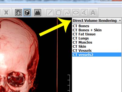
The listbox for choosing current rendering mode in 3D.
 |
Direct Volume Rendering. It is the only rendering mode that requires transfer function (preset) as a visualization parameter. Other rendering algorithms in InVols use only WL setting, which can be altered with |
 | Direct Volume Rendering(WL). It is a special case of DVR with TF. This method uses grey-scaled transfer function. |
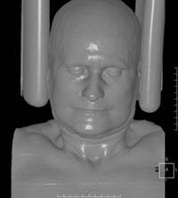 | Shaded surface. Iso-surface rendering, where iso-value equals window center minus half of window width. |
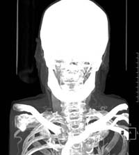 | MIP Maximum Intensity Projection. |
These two options for volumetric visualization can be found in the "Settings" menu. Shading is usually used to improve spatial perception of the surface, while tricubic filtering sometimes reduces rendering artifacts. Each of these options, especially tricubic filtering, considerably affect rendering performance.
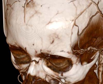 |
 |
| Trilinear interpolation | Tricubic interpolation |
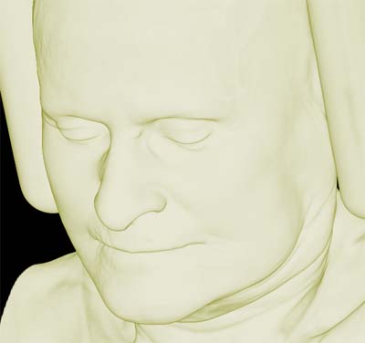 |
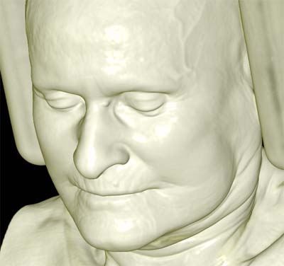 |
| No shading | With shading |
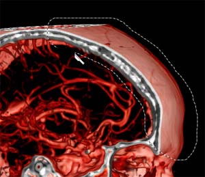
This instrument allows for manual contouring and deletion of spatial structures which may occlude features of interest. Tools below are used to manage cutting:
| Switch to cutting mode. | |
| Cancel last cut operation. | |
| Cancel all cut operations. |
 |
 |
When "3D rendering on GPU" option in "Settings" menu turned off the rendering process will be switched from GPU to CPU, thus escaping the need for any GPU at all. However real-time Direct Volume Rendering algorithms is still computationally too expensive for CPU.
Double-click on the window with 3D output switches to multi-view mode or backwards.
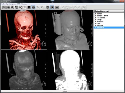
Rendering into several windows. Each view has its own rendering settings. In common they have: dataset, camera, cutting, bounding box.